


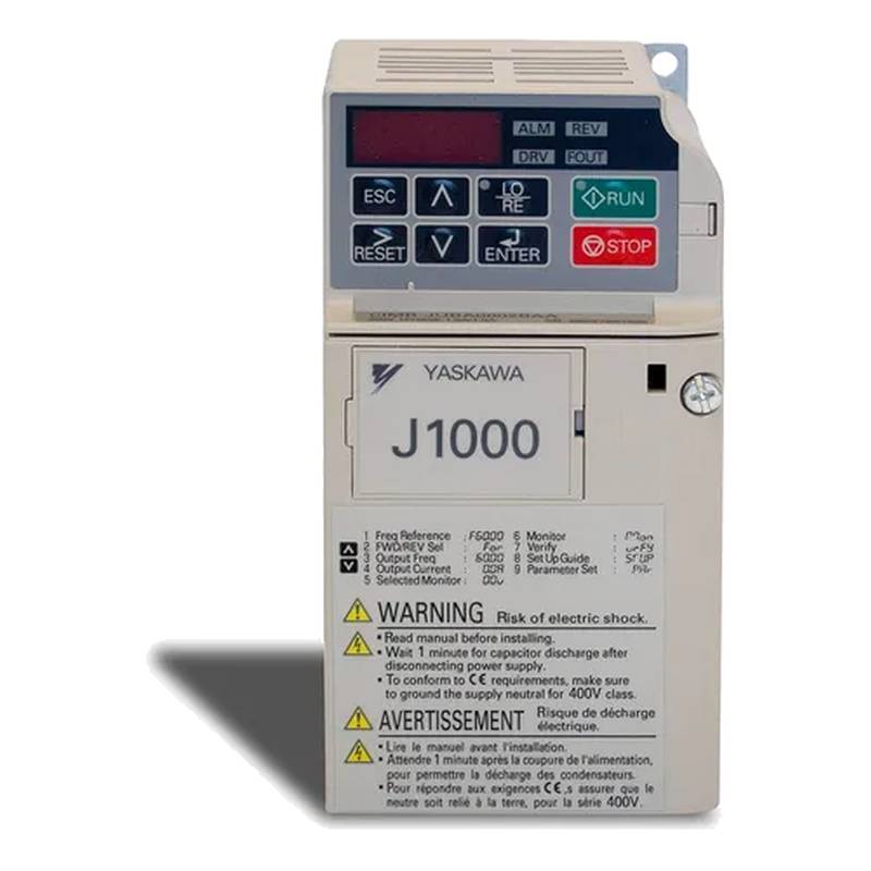
Yaskawa JB4A0011BBA J1000 Motor Control Industrial VFD Frequency Converter 9.2A 3.7kW


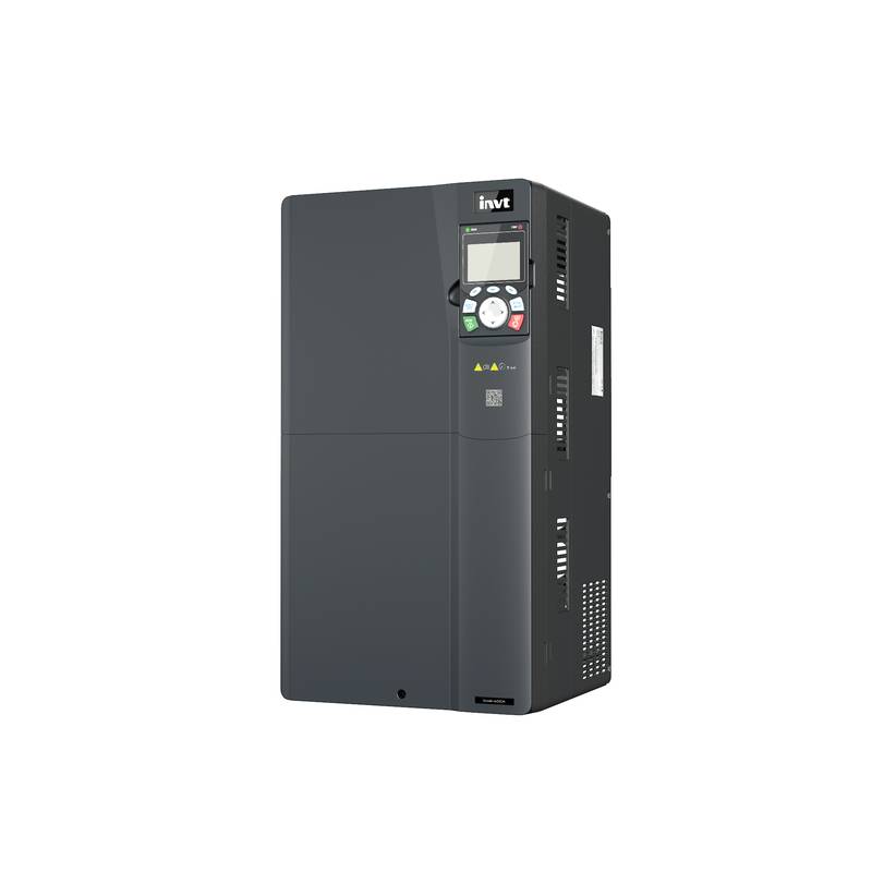
The Yaskawa J1000 VFD (Variable Frequency Drive), model JB4A0011BBA, is engineered for precise motor control in a wide array of industrial applications. This 3.7kW (5HP) unit operates with a 9.2A current rating, offering robust performance and energy efficiency. Its compact design, advanced digital control, and user-friendly interface make it a superior choice for machinery requiring variable speed operation, including conveyors, pumps, fans, and machine tools. The J1000 series is distinguished by its high starting torque capabilities and advanced protective features, ensuring reliable operation and extended equipment lifespan in demanding environments.
Product Specifications
| Feature | Specification |
| :---------------------- | :---------------------------- |
| Model | Yaskawa JB4A0011BBA J1000 |
| Power | 3.7 kW (5 HP) |
| Current Rating | 9.2 A |
| Input Voltage | 3-Phase 200-240V AC |
| Output Voltage | 3-Phase 200-240V AC |
| Frequency Range | 0.0 to 400.0 Hz |
| Control Method | V/f Control, Closed Loop Vector |
| Protection Class | IP20 |
| Dimensions (H x W x D) | 245 x 140 x 169 mm |
| Ambient Temperature | -10 to +50 °C |
Core Features & Market Positioning
The Yaskawa J1000 JB4A0011BBA stands out in the industrial VFD market due to its exceptional reliability and versatile control capabilities. Its advanced digital control technology ensures precise speed regulation and torque control, which are critical for applications demanding high accuracy. This VFD offers superior energy savings by optimizing motor speed based on load requirements, directly impacting operational costs. The unit's robust design and comprehensive protection features, including overload and short-circuit protection, position it as a durable and dependable solution for continuous industrial operations. Furthermore, its intuitive programming interface and built-in safety functions facilitate seamless integration and operation, setting it apart from many competitors.
Key Application Scenarios
This Yaskawa J1000 VFD is ideally suited for a broad spectrum of industrial applications where variable speed and precise motor control are paramount. It excels in driving centrifugal pumps and fans, optimizing fluid and air flow while reducing energy consumption. In material handling systems, such as conveyors and automated warehousing, its precise speed adjustment ensures smooth product transfer and efficient operation. Machine tool applications benefit from the J1000's ability to deliver high starting torque and accurate speed holding for cutting and machining processes. Other common uses include textile machinery, packaging equipment, and general-purpose industrial motor speed control, where efficiency and reliability are key performance indicators.
Practical System Integration Guidance
Integrating the Yaskawa JB4A0011BBA J1000 into an industrial system is streamlined by its user-friendly design. Ensure the drive is installed in a well-ventilated area, adhering to the specified ambient temperature range of -10 to +50 °C, and within its IP20 protection rating limitations. Proper wiring is crucial: connect the 3-phase 200-240V AC input power to the designated terminals, and the motor leads to the output terminals. For control signals, utilize the low-voltage terminals for start/stop commands, speed reference signals (e.g., 0-10V DC or 4-20mA), and potential interlocks. Parameter programming is accessible via the integrated keypad and display, allowing for customization of acceleration/deceleration times, base frequency, and motor data. Referencing the Yaskawa J1000 manual is recommended for detailed wiring diagrams and advanced parameter setup, such as closed-loop vector control configurations.
Operation and Risk Mitigation
Operating the Yaskawa J1000 VFD JB4A0011BBA requires adherence to safety protocols to mitigate risks. Before powering on, verify all connections are secure and that the motor parameters are correctly configured in the VFD. Avoid operation beyond the specified 3.7kW power and 9.2A current ratings to prevent overload. Common error codes, such as "E1" (overcurrent) or "E5" (overload), typically indicate issues with motor load, wiring, or drive settings. Implementing proper motor tuning during commissioning helps prevent mechanical stress and potential failures. Ensure adequate cooling and ventilation for the drive to maintain optimal operating temperature and prevent thermal shutdown. Regular visual inspections of wiring and component integrity are also advised.
Scalability & Long-Term Value
The Yaskawa J1000 VFD, model JB4A0011BBA, offers significant long-term value through its inherent scalability and integration capabilities within modern industrial environments. While the J1000 is a robust standalone solution, Yaskawa's broader product ecosystem allows for seamless upgrades to more advanced drives like the A1000 or V1000 series if future application requirements demand enhanced features or higher capacities. Its compatibility with standard industrial communication protocols (e.g., Modbus RTU via optional communication modules) enables integration into SCADA systems and broader IIoT platforms, facilitating remote monitoring, diagnostics, and predictive maintenance. This foresight in design ensures that investments in Yaskawa technology remain relevant and adaptable to evolving industry standards and the digital transformation of manufacturing.
Frequently Asked Questions (FAQs)
1. What are the main benefits of using the Yaskawa J1000 JB4A0011BBA?
This VFD offers precise motor speed control and significant energy savings by matching motor output to the load requirement. Its robust construction ensures high reliability in demanding industrial settings.
It provides excellent starting torque, crucial for applications with heavy loads, and features comprehensive protection functions for operational safety. The user-friendly interface simplifies setup and adjustments for various applications.
The J1000's compact design facilitates installation in space-constrained environments, and its advanced digital control technology contributes to smoother machine operation and reduced wear.
2. How do I wire the Yaskawa J1000 JB4A0011BBA for a simple start/stop application?
Connect the three-phase 200-240V AC power supply to the main input terminals (L1, L2, L3). Ensure proper grounding for safety.
For a basic start/stop, connect a contact closure from an external switch or PLC output to the digital input terminals designated for start (e.g., DI1) and stop (e.g., DI2).
Connect the three motor leads (U, V, W) to the VFD's output terminals, ensuring correct phase rotation for the motor. Refer to the manual for specific terminal assignments.
3. What is the typical application for a 3.7kW, 9.2A Yaskawa J1000 drive?
This drive is ideal for medium-sized industrial equipment such as pumps, fans, and compressors requiring variable speed operation for efficiency. It's also well-suited for conveyor systems, mixers, and extruders in manufacturing and processing industries.
Applications in HVAC systems benefit from precise airflow and pressure control, leading to reduced energy consumption and improved comfort levels. Machine tool applications, like CNC machines or lathes, utilize its high starting torque and accurate speed regulation for cutting performance.
The Yaskawa J1000 JB4A0011BBA is also commonly used in packaging machinery, textile equipment, and general-purpose motor speed control where adjustable speed is a key operational requirement.
4. Can the Yaskawa J1000 JB4A0011BBA be used with single-phase motors?
No, the Yaskawa J1000 JB4A0011BBA is designed to control three-phase AC induction motors. It requires a three-phase input power supply to operate correctly.
While it controls three-phase motors, it can sometimes be used with single-phase motors if a phase converter is employed to supply a three-phase input to the VFD. However, this is not the intended or most efficient use.
Always ensure the motor connected to the VFD is a three-phase motor rated for the voltage and frequency output of the drive for optimal performance and safety.
5. What are common causes of the E1 (Overcurrent) fault on the J1000 drive?
An E1 fault often indicates that the motor is drawing more current than the drive is programmed to allow, usually due to a mechanical overload on the driven equipment. Check for jammed machinery or excessive load conditions.
Wiring issues can also trigger this fault; ensure the motor leads (U, V, W) are securely connected to the VFD output terminals and that there are no short circuits between them or to ground. Incorrect motor parameters programmed into the VFD can also lead to overcurrent readings.
Another possibility is that the acceleration time is set too short for the application, causing the motor to demand excessive current during startup. Adjusting the acceleration time parameter can often resolve this specific cause.
6. How do I set up the acceleration and deceleration times for the Yaskawa J1000?
Access the drive's parameter menu and locate the acceleration time (often labeled ACC or tAcc) and deceleration time (often labeled DEC or tDec) parameters. These are typically found in the basic parameter group.
Enter the desired time in seconds for both acceleration and deceleration based on the requirements of your application. For example, a gradual start might require 10 seconds, while an emergency stop might need a much shorter deceleration time.
Consider the inertia of the driven load and the required smoothness of operation. Overly short times can cause mechanical stress or overcurrent faults, while excessively long times may reduce productivity.
7. What is the IP rating of the Yaskawa J1000 JB4A0011BBA and what does it mean for installation?
The Yaskawa J1000 JB4A0011BBA has an IP20 rating. This means it is protected against solid objects greater than 12.5 mm (like a finger) but offers no protection against water or dust ingress.
Due to its IP20 rating, the drive must be installed in a clean, dry environment, typically within an enclosure or control panel, to prevent damage from dust, moisture, or foreign objects.
Adequate ventilation is crucial for IP20 rated equipment as it relies on free air circulation for cooling. Ensure that the enclosure allows for sufficient airflow around the drive to prevent overheating.
8. How can I perform motor auto-tuning on the Yaskawa J1000 drive?
Ensure the motor is connected to the VFD and that basic motor parameters (like voltage, frequency, and RPM) are correctly entered. The drive should be at rest, not running.
Navigate to the auto-tuning function within the VFD's parameter settings. There are typically two types: static tuning (performed with the motor stationary) and dynamic tuning (performed while the motor is rotating).
Initiate the auto-tuning process. The drive will send signals to the motor to measure its electrical characteristics and then automatically adjust its internal parameters for optimal performance, especially for closed-loop vector control.
9. What is the maximum output frequency for the Yaskawa J1000 JB4A0011BBA?
The Yaskawa J1000 J1000 VFD can operate with a maximum output frequency of up to 400.0 Hz. This allows for a wide range of speed control capabilities for various motor types and applications.
This high frequency output is particularly useful in applications requiring very high motor speeds, such as certain types of machine tools or high-speed fans and pumps. It offers flexibility in matching motor speed to specific process requirements.
However, always ensure that the motor connected is rated to safely operate at the selected output frequency, considering factors like bearing limitations and thermal capacity.
10. Can I use an external potentiometer to control the speed of the motor with this VFD?
Yes, the Yaskawa J1000 JB4A0011BBA supports speed control via an external potentiometer. Connect the potentiometer to the designated analog input terminals on the drive.
Configure the VFD's parameters to accept the analog voltage signal from the potentiometer as the speed reference. This typically involves setting the analog input function and scaling its range to match the potentiometer's output.
Ensure the potentiometer is of appropriate value (e.g., 1kΩ to 10kΩ) and properly wired to the drive's low-voltage control terminals for accurate speed adjustment.