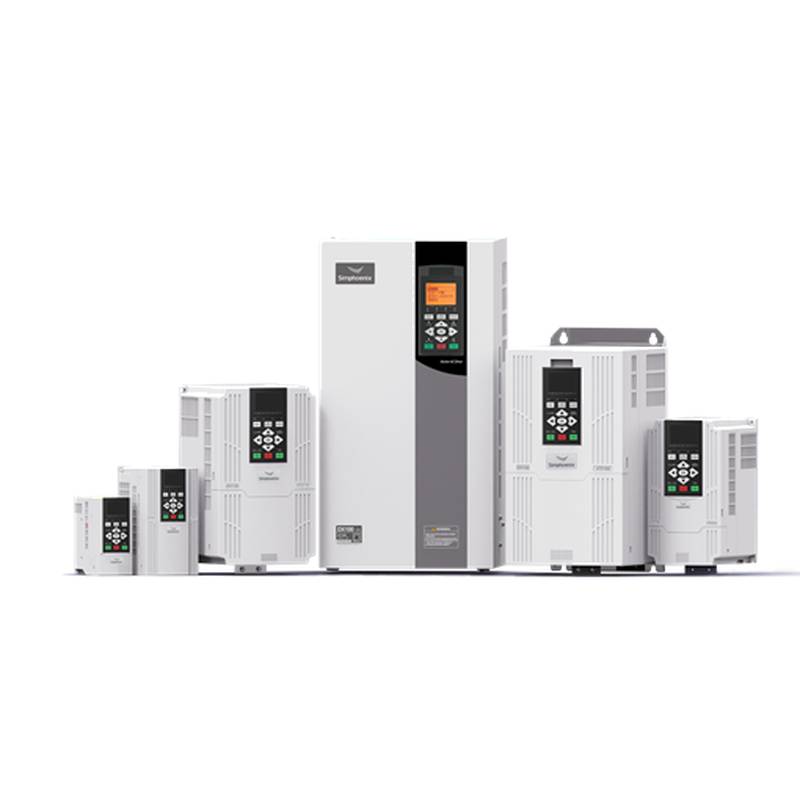


DANFOSS FC-301P4K0T4E20H2XGCXXXSXXXXAXBXCXXXXDX 4kW 480V Three Phase Automation Inverter


The DANFOSS FC-301P4K0T4E20H2XGCXXXSXXXXAXBXCXXXXDX 4kW 480V Three Phase Automation Inverter is a robust and intelligent drive engineered for demanding industrial applications, offering exceptional precision, energy efficiency, and seamless integration. This advanced inverter boasts a 4kW power rating and operates on a 480V three-phase supply, making it ideal for controlling a wide array of motor-driven processes. Its core advantages lie in its superior motor control algorithms, enhanced thermal management, and extensive programmability, ensuring optimal performance and longevity in critical automation systems. The FC-301P series exemplifies Danfoss's commitment to innovation, delivering reliable power conversion and sophisticated control for modern industrial environments.
Product Specifications
| Parameter | Value |
|---|---|
| Model Number | FC-301P4K0T4E20H2XGCXXXSXXXXAXBXCXXXXDX |
| Power Rating | 4 kW |
| Voltage Rating | 480V |
| Phase | Three Phase |
| Protection Class | IP20 |
| Enclosure Type | Open chassis (for cabinet installation) |
| Maximum Output Frequency | 600 Hz |
| Control Method | VVCplus (Vector Voltage Control plus), Advanced V/f, Flux Vector Control |
| Overload Capacity | 150% for 60 seconds, 200% for 3 seconds |
| Ambient Temperature Range | 0°C to 50°C (derating above 40°C) |
| Harmonic Distortion | Built-in harmonic mitigation options available |
| Communication Options | Modbus RTU, PROFINET, EtherNet/IP, PROFIBUS DP (module dependent) |
Core Features & Market Positioning
The DANFOSS FC-301P4K0T4E20H2XGCXXXSXXXXAXBXCXXXXDX 4kW 480V inverter stands out in the market due to its advanced VVCplus (Vector Voltage Control plus) technology, which provides precise motor speed and torque control, even under fluctuating loads. This level of control is crucial for applications requiring dynamic response and consistent performance. Its market positioning is firmly established as a high-performance, reliable solution for complex automation tasks where energy savings and operational efficiency are paramount. The inverter's robust design and thermal management capabilities allow for operation in challenging industrial environments, differentiating it from less capable competitors. Danfoss's reputation for quality and long-term support further solidifies its competitive edge.
Key Application Scenarios
This 4kW, 480V three-phase automation inverter is exceptionally well-suited for a diverse range of industrial applications. Its precise control makes it ideal for conveyor systems, pumps, fans, and mixers where variable speed is essential for process optimization and energy conservation. In the manufacturing sector, it finds application in machine tools and packaging machinery, ensuring smooth operation and high throughput. Furthermore, its robust construction and advanced features make it a reliable choice for HVAC systems in commercial buildings and for process control in the water and wastewater industries. The ability to handle dynamic loads and provide accurate speed regulation ensures efficiency and reduces wear on mechanical components across these varied scenarios.
Practical System Integration Guidance
Integrating the DANFOSS FC-301P4K0T4E20H2XGCXXXSXXXXAXBXCXXXXDX into an existing system requires careful consideration of power and control wiring. For optimal performance and safety, the inverter should be installed in a well-ventilated control cabinet to maintain its operating temperature within specifications, especially given its IP20 rating. Utilize shielded motor cables to minimize electromagnetic interference (EMI). Ensure the supply voltage of 480V three-phase is correctly connected to the L1, L2, and L3 terminals. For control signals, a separate low-voltage supply is typically used for the digital and analog inputs/outputs, adhering to the voltage ratings specified in the user manual. Proper grounding of the inverter chassis and motor is critical to prevent electrical hazards and ensure reliable operation. Commissioning involves parameter setup, including motor data entry for optimal autotuning, setting speed references, and configuring I/O functions according to the specific application requirements.
Operation and Risk Mitigation
Safe and efficient operation of the DANFOSS FC-301P4K0T4E20H2XGCXXXSXXXXAXBXCXXXXDX inverter hinges on adherence to operational protocols and understanding potential fault conditions. Always ensure the drive is de-energized before performing any wiring or maintenance. Emergency stop functionality must be integrated into the system logic to quickly bring the motor to a safe halt in case of critical events. Common troubleshooting may involve addressing overcurrent or overvoltage faults, which can often be mitigated by checking motor load, cable lengths, and input power quality. Understanding the inverter's diagnostic messages and error codes, accessible via the control panel or communication interface, is crucial for swift fault resolution. For example, a "Motor Overload" warning might indicate a need to adjust acceleration ramps or reduce the mechanical load.
Scalability & Long-Term Value
The DANFOSS FC-301P4K0T4E20H2XGCXXXSXXXXAXBXCXXXXDX inverter offers significant scalability and long-term value through its compatibility with Danfoss's broad ecosystem of automation components and its inherent IIoT readiness. This drive can be easily integrated into larger Distributed Control Systems (DCS) or Supervisory Control and Data Acquisition (SCADA) systems using optional communication modules for protocols like PROFINET or EtherNet/IP, enabling centralized monitoring and control. Its modular design also allows for future expansion of I/O capabilities or communication interfaces as application demands evolve. By providing precise motor control and optimizing energy consumption, the FC-301P series contributes to reduced operational costs and a longer lifespan for connected machinery, thereby maximizing the return on investment.
Frequently Asked Questions
What is the maximum power output of the DANFOSS FC-301P4K0T4E20H2XGCXXXSXXXXAXBXCXXXXDX?
The DANFOSS FC-301P4K0T4E20H2XGCXXXSXXXXAXBXCXXXXDX has a rated power output of 4 kilowatts (kW). This power rating is suitable for a wide range of industrial motor applications. It is designed to drive motors that require significant torque and speed control capabilities.
This 4kW capacity ensures efficient operation for many common industrial machinery types. It can handle substantial mechanical loads and dynamic performance requirements. The inverter's robust design ensures reliable power delivery even under demanding conditions.
The specified power is the continuous output capability. For short durations, the inverter can often handle higher peak loads. Always consult the product's technical documentation for precise overload specifications.
What are the primary control modes supported by this inverter?
This inverter supports multiple advanced control modes, including VVCplus (Vector Voltage Control plus), Advanced V/f, and Flux Vector Control. These modes offer precise control over motor speed and torque. VVCplus is particularly noted for its high performance in dynamic applications.
These control strategies allow the drive to adapt to various motor types and application demands. They ensure optimal efficiency and responsiveness, reducing energy consumption and improving process accuracy. Users can select the mode that best suits their specific motor and operational needs.
Choosing the right control mode is crucial for maximizing performance and energy savings. The inverter's flexibility allows for fine-tuning to achieve superior motor performance and extended equipment life. Proper configuration ensures the drive operates at its peak efficiency.
How do I perform an autotune on the DANFOSS FC-301P4K0T4E20H2XGCXXXSXXXXAXBXCXXXXDX?
Autotuning is a critical step for optimizing the inverter's performance with your specific motor. You will typically access the autotuning function through the inverter's control panel or programming software. The process requires the motor to be connected and stationary initially.
During autotuning, the inverter measures the motor's electrical parameters like resistance and inductance. It then uses this data to calibrate its control algorithms for maximum efficiency and torque. Ensure you follow the sequence and safety precautions outlined in the user manual.
After the autotune is complete, the measured motor data is stored in the inverter's memory. This significantly enhances the motor's dynamic response and overall control accuracy. Always verify the autotune results and make manual adjustments if necessary for specialized applications.