











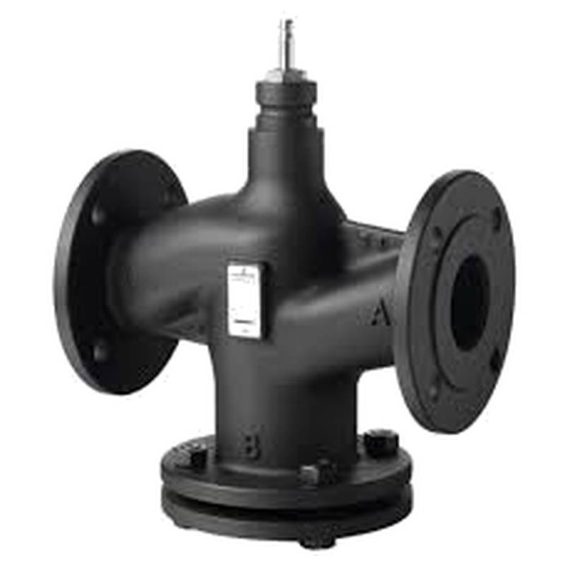
SIEMENS VVF53.25-8 Two-Way Valve DN25 kvs 8.0 Standard


The SIEMENS VVF53.25-8 Two-Way Valve DN25 kvs 8.0 Standard is a precisely engineered control valve designed for demanding HVAC and industrial automation applications. This valve offers exceptional flow control accuracy with its KVS rating of 8.0 m³/h, ensuring optimal system performance and energy efficiency. Its robust construction and reliable Siemens actuation mechanisms make it a cornerstone for precise temperature regulation and fluid management in Building Management Systems (BMS) and various industrial processes. Key advantages include its compact design, high sealing integrity, and compatibility with standard Siemens actuators, facilitating straightforward integration and long-term operational stability.
Product Specifications
| Specification | Value |
| :--------------------- | :----------------------------------------- |
| Product Type | Two-Way Control Valve |
| Manufacturer | SIEMENS |
| Model | VVF53.25-8 |
| Nominal Size (DN) | 25 |
| Flow Coefficient (kvs) | 8.0 m³/h |
| Connection Type | Flanged (typically) |
| Body Material | Cast Iron (GG25) |
| Seat Material | EPDM rubber |
| Max. Differential Pressure | 100 kPa (1 bar) |
| Temperature Range | -10...+120 °C |
| Actuator Compatibility | Siemens electric actuators (e.g., GQD, GLB) |
| Sealing | Tight-closing (EN 60742 Class IV) |
Core Features & Market Positioning
The SIEMENS VVF53.25-8 distinguishes itself through its superior flow control characteristics and robust design, making it a preferred choice for applications demanding precision and reliability. Its tight-closing capability, meeting EN 60742 Class IV, minimizes energy waste by preventing unwanted flow when closed. This valve is engineered for seamless integration with Siemens' comprehensive range of actuators and control systems, offering a unified and efficient automation solution. In the competitive landscape of industrial control valves, the VVF53.25-8 stands out for its balanced performance, durability, and the trusted Siemens brand reputation for quality and innovation.
Key Application Scenarios
This two-way control valve is extensively utilized in HVAC systems for precise control of hot and cold water in heating and cooling circuits. It is ideal for modulating the flow to terminal units such as fan coil units, air handling units, and radiators, ensuring optimal room temperature comfort and energy conservation. In industrial settings, the VVF53.25-8 is applied in process control loops requiring accurate fluid management, including temperature regulation of machinery, control of steam, or other industrial fluids within its specified operating parameters. Its DN25 size and kvs 8.0 rating make it suitable for medium-flow applications where precise throttling is essential.
Practical System Integration Guidance
Integrating the SIEMENS VVF53.25-8 valve requires careful consideration of the actuator selection and control signal. Siemens offers a variety of electric actuators, such as the GQD series for on/off or 3-point control, and the GLB series for modulating control (typically 0-10V or 4-20mA signals), which must be compatible with the valve's stem and stroke. Ensuring the correct actuator is selected based on the required torque and stroke length is critical for proper operation. Piping connections should be made according to standard flanged connections, ensuring proper gasket seating and bolt torquing to prevent leaks. The valve should be installed in a configuration that allows for easy actuator maintenance and access.
Operation and Risk Mitigation
Proper operation of the SIEMENS VVF53.25-8 valve relies on maintaining fluid temperatures and pressures within its specified limits to prevent damage. Regular inspection of the valve and actuator for any signs of wear, leaks, or unusual noise is recommended. In the event of actuator failure, a manual override feature, if available on the chosen actuator, can provide temporary control. While specific error codes are typically associated with the actuator and control system rather than the valve itself, common issues might include actuator not responding, which could indicate a wiring problem, a faulty actuator, or an incorrect control signal. Ensuring the system is properly flushed before commissioning helps prevent debris from damaging valve seats.
Scalability & Long-Term Value
The SIEMENS VVF53.25-8 valve offers significant long-term value through its compatibility with Siemens' broader automation ecosystem. It can be easily integrated into advanced Building Management Systems (BMS) or SCADA systems, enabling centralized monitoring and control. This integration supports the adoption of Industrial Internet of Things (IIoT) strategies, allowing for data collection on valve performance, predictive maintenance, and optimization of energy consumption. The availability of spare parts and Siemens' global support network ensures the longevity and continued reliable performance of the valve within evolving industrial and building automation infrastructures.
Frequently Asked Questions
What is the maximum operating pressure for the SIEMENS VVF53.25-8?
The valve body is rated for a maximum differential pressure of 100 kPa (1 bar). This ensures reliable operation in many standard HVAC applications. Exceeding this limit can lead to premature wear or failure of valve components.
This specification is crucial for system designers to avoid over-pressurization. It directly impacts where the valve can be safely installed within a hydraulic circuit.
Always consult the full datasheet for precise operating envelopes and limitations. It is essential to verify system pressure against these limits.
How do I select the correct Siemens actuator for the VVF53.25-8 valve?
Actuator selection depends on whether modulating or on/off control is needed. Consider the required torque, stroke length, and control signal type (e.g., 0-10V, 4-20mA, 3-point). Siemens offers actuators like the GQD and GLB series for this valve.
Refer to Siemens' actuator selection guides for detailed compatibility charts. These guides match valve characteristics with actuator performance capabilities.
Ensure the chosen actuator's mounting dimensions and shaft connection match the valve's specifications precisely for a secure and functional integration.
What is the meaning of DN25 and kvs 8.0 for this valve?
DN25 refers to the nominal diameter of the valve, approximately 25mm, indicating its pipe connection size. The kvs 8.0 signifies the flow coefficient, meaning the valve can pass 8.0 cubic meters of water per hour at a 1-bar pressure drop.
This kvs value is critical for hydraulic balancing and sizing control loops. It dictates the maximum flow rate the valve can handle at a given pressure differential.
Understanding these parameters is fundamental for correct application sizing and ensuring system performance meets design intent. It allows engineers to calculate flow rates at various positions and pressures.