


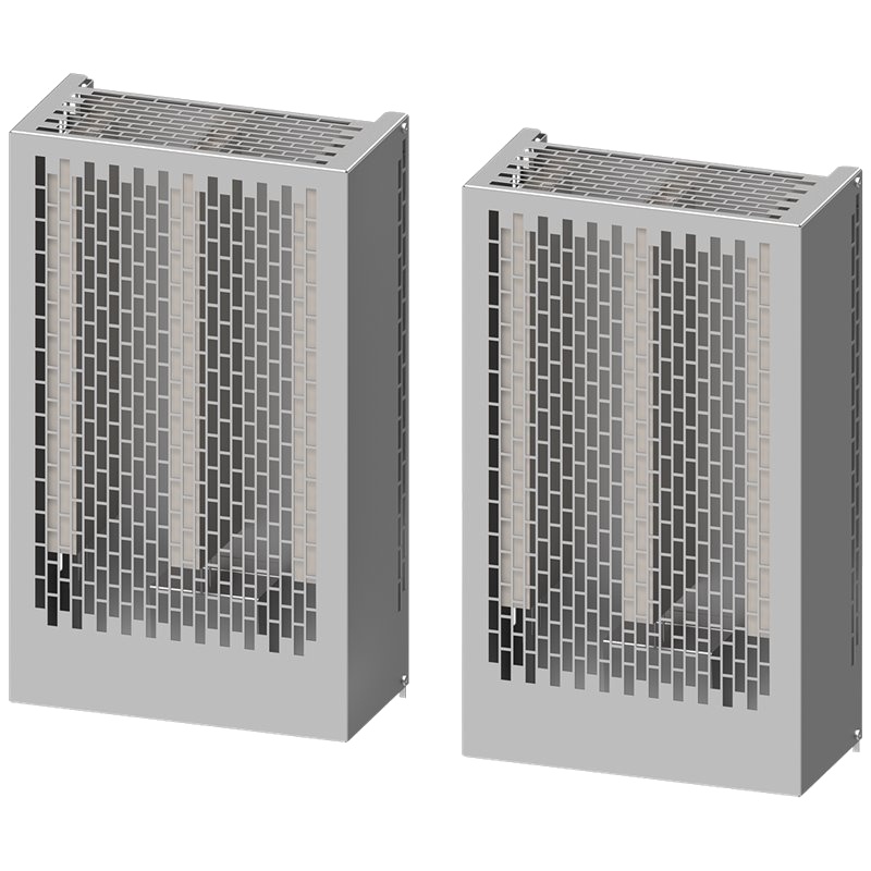
SIEMENS 6SL3201-0BE21-0AA0 SINAMICS Braking Resistor 380V-480V 670 Ohm 200W 4000W for FSB


The SIEMENS 6SL3201-0BE21-0AA0 SINAMICS braking resistor is a critical component for managing dynamic braking in motor control applications. This unit offers significant advantages, including enhanced system safety and extended equipment lifespan by dissipating excess energy during deceleration. Key technical parameters include an operating voltage range of 380V-480V, a resistance of 670 Ohms, a continuous power rating of 200W, and a peak power rating of 4000W, specifically designed for FSB (Fast-Speed Braking) applications.
Product Specifications
| Parameter | Value |
| :-------------------- | :--------------------- |
| Manufacturer | Siemens |
| Product Series | SINAMICS |
| Product Number | 6SL3201-0BE21-0AA0 |
| Type | Braking Resistor |
| Voltage Rating | 380V-480V |
| Resistance | 670 Ohm |
| Continuous Power | 200W |
| Peak Power | 4000W |
| Application | Fast-Speed Braking (FSB) |
| Protection Class | IP20 |
| Ambient Temperature | -20°C to +40°C |
Core Features & Market Positioning
The SIEMENS 6SL3201-0BE21-0AA0 stands out in the industrial automation market due to its robust construction and precise energy dissipation capabilities, making it a preferred choice for demanding applications. Its integration within the SINAMICS drive family ensures seamless compatibility and optimized performance with Siemens variable frequency drives (VFDs). This resistor is engineered to handle significant inductive energy generated during rapid motor deceleration, preventing overvoltage on the drive's DC bus and safeguarding sensitive electronic components. The unit’s high peak power rating ensures it can absorb short, intense energy bursts, a crucial differentiator in applications requiring frequent and aggressive braking. Its market positioning is firmly established as a reliable, high-performance solution for industrial motor control where safety and equipment longevity are paramount.
Key Application Scenarios
This SIEMENS SINAMICS braking resistor (6SL3201-0BE21-0AA0) is ideally suited for industrial environments where rapid and controlled deceleration of motor loads is essential. Common applications include material handling systems, such as conveyors and cranes, where quick stopping is required to prevent collisions or ensure precise positioning. It is also vital in machine tool applications, like CNC machines and presses, to achieve accurate stopping for operational safety and workpiece integrity. Furthermore, its use is prevalent in the manufacturing sector for applications involving elevators, escalators, and automated warehousing systems where energy management during stopping cycles is critical for operational efficiency and safety compliance. The 380V-480V rating makes it versatile for global industrial power grids.
Practical System Integration Guidance
Integrating the SIEMENS 6SL3201-0BE21-0AA0 braking resistor into a SINAMICS drive system is a straightforward process. It connects directly to the DC bus terminals of compatible SINAMICS drives, typically marked as "B+" and "BM" (or similar). Proper wiring is crucial; ensure the resistor is securely fastened and all connections are tight to prevent arcing and ensure optimal heat dissipation. The drive’s parameter settings must be configured to recognize and utilize the braking resistor. This involves enabling the braking chopper function and setting the threshold voltage for braking resistor activation within the drive's control parameters, often found in dedicated braking configuration menus. Always consult the specific SINAMICS drive's manual for precise parameter names and values.
Operation and Risk Mitigation
Safe operation of the SIEMENS 6SL3201-0BE21-0AA0 braking resistor requires adherence to installation and operational guidelines. The resistor generates significant heat during operation; therefore, it must be installed in a well-ventilated area, away from flammable materials, and with adequate clearance as specified by Siemens. Monitoring the resistor's temperature is advisable, especially in high-duty cycle applications. Common troubleshooting involves checking for open circuits or shorts in the resistor element and wiring, and ensuring the drive's braking parameters are correctly set. Overvoltage faults on the drive often indicate an issue with the braking resistor circuit or its configuration, prompting a system check. Always disconnect power before performing any maintenance.
Scalability & Long-Term Value
The SIEMENS 6SL3201-0BE21-0AA0 braking resistor offers excellent long-term value through its compatibility with a wide range of SINAMICS drives, allowing for flexible system design and upgrades. Its robust build ensures a long operational lifespan, reducing the total cost of ownership. For systems requiring higher braking power, multiple resistors can sometimes be paralleled or series-connected, depending on the drive's capabilities and the specific application requirements, though this must be carefully calculated and validated with Siemens technical support. Integration into modern industrial automation platforms, including those leveraging Industrial Internet of Things (IIoT) concepts, is facilitated by the SINAMICS drive's connectivity features, allowing for remote monitoring and diagnostics of the braking resistor's performance status.
Frequently Asked Questions
What is the purpose of the SIEMENS 6SL3201-0BE21-0AA0 braking resistor?
This resistor absorbs excess energy during motor deceleration. It prevents overvoltage on the drive's DC bus. This protects the drive's electronic components.
The SIEMENS 6SL3201-0BE21-0AA0 is crucial for applications needing quick stops. It dissipates kinetic energy safely. This extends the lifespan of motor and drive systems.
It acts as a load for the drive's braking chopper. The resistor converts electrical energy into heat. This controlled energy dissipation is vital for system stability and safety.
What are the key technical specifications of the 6SL3201-0BE21-0AA0?
It operates within a 380V to 480V voltage range. The resistor has a value of 670 Ohms. Its continuous power rating is 200W.
The peak power rating is substantial at 4000W. This allows it to handle high-energy braking events. It is designed for Fast-Speed Braking (FSB) applications.
The unit has an IP20 protection class. It is suitable for ambient temperatures from -20°C to +40°C. These specs define its operating envelope.
How do I connect the SIEMENS 6SL3201-0BE21-0AA0 to a SINAMICS drive?
Connect the resistor terminals to the drive's DC bus terminals. These are typically labeled B+ and BM. Ensure secure and clean connections.
Follow the wiring diagram in the drive's manual. Proper polarity is generally not an issue for resistors. However, always verify with documentation.
Use appropriate gauge wiring for the current loads. Ensure the resistor is properly grounded if required by the system design.
What is the role of the braking resistor in a SINAMICS drive system?
It dissipates excess energy generated during motor braking. This energy comes from the motor's inertia. Without it, DC bus voltage could rise dangerously high.
The braking resistor works with the drive's braking chopper. The chopper activates when the DC bus voltage exceeds a set limit. It then directs energy to the resistor.
This prevents overvoltage trips and protects drive components. It allows for faster and more controlled motor stops. Essential for dynamic applications.
What are the typical applications for the 6SL3201-0BE21-0AA0?
Material handling equipment like cranes and conveyors. Machine tools requiring precise stopping. Automated manufacturing processes with high cycle rates.
Elevators and escalators benefit from controlled braking. Hoists and winches in industrial settings use this. Any application needing rapid deceleration of rotating loads.
Its 380-480V rating suits many industrial power systems. It is vital for applications where energy recovery is not feasible or sufficient.
How is the braking resistor configured in the SINAMICS drive parameters?
Enable the braking chopper function in the drive's settings. Set the DC bus overvoltage trip point. This threshold should be below the drive's maximum voltage limit.
Configure the braking resistor parameters. This includes resistance value and possibly power ratings. Some drives may have specific resistor type selections.
Refer to the specific SINAMICS drive manual for exact parameter numbers. Incorrect settings can lead to faults or reduced braking performance.
What safety precautions should be taken when installing or operating this resistor?
Ensure the resistor is installed in a well-ventilated area. Avoid mounting near flammable materials. Maintain recommended clearance distances.
Always disconnect power to the drive before working on the resistor. The resistor can become very hot during operation. Allow it to cool before touching.
Verify all electrical connections are secure. Use appropriate personal protective equipment (PPE). Follow local electrical codes and safety regulations.
What is the continuous power rating versus peak power rating for this resistor?
The continuous power rating is 200W. This is the power it can dissipate indefinitely. It defines the resistor's thermal limit for constant loads.
The peak power rating is 4000W. This is the maximum power it can handle for short durations. It is crucial for dynamic braking events.
The peak rating ensures the resistor can absorb sudden energy surges. This is typical during rapid deceleration cycles. It prevents overheating during these transient states.
Can this braking resistor be used with non-SINAMICS drives?
Generally, it is designed for Siemens SINAMICS drives. Compatibility with other drive brands is not guaranteed. Integration requires careful technical verification.
External braking resistors need specific drive support. The drive must have a braking chopper and configurable parameters. Voltage and resistance matching is critical.
Using it with incompatible drives may cause damage or failure. Always consult drive manufacturer documentation for external resistor compatibility.
How do I troubleshoot issues with the SIEMENS 6SL3201-0BE21-0AA0?
Check for physical damage to the resistor element. Inspect wiring for loose connections or breaks. Ensure the resistor is correctly wired to the drive terminals.
Verify the drive parameters for braking configuration. Ensure the braking chopper is enabled and thresholds are set correctly. Check for overvoltage faults in the drive's status.
Test the resistor's resistance value with a multimeter. Compare it to the specified 670 Ohms. If the value is significantly different, the resistor may be faulty.