


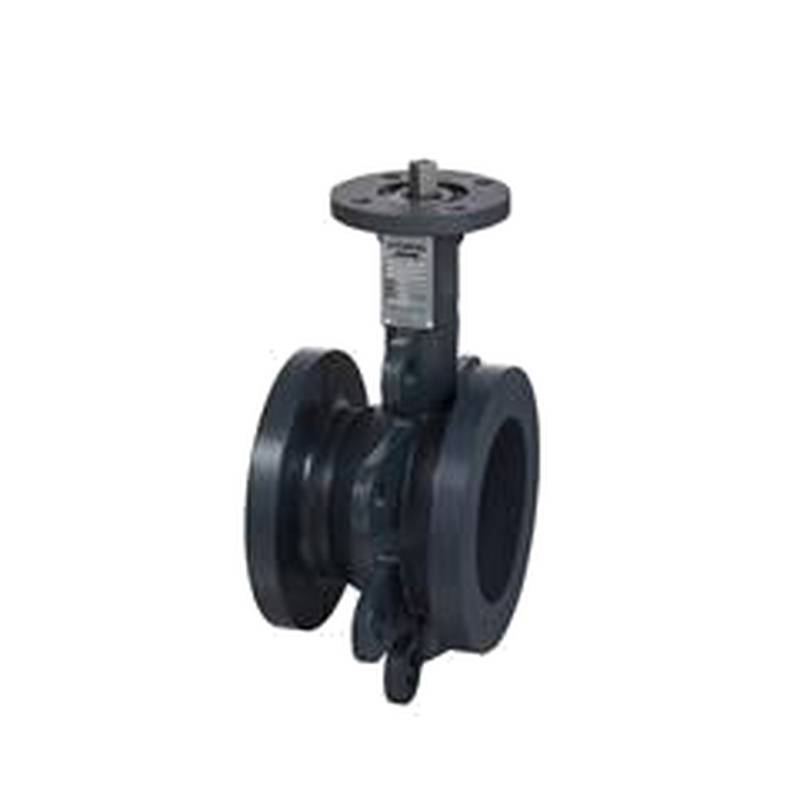
SIEMENS VAI61.25-16 Two-Way Ball Valve DN25 kvs 16 VAI61


The SIEMENS VAI61.25-16 Two-Way Ball Valve (DN25, kvs 16) stands as a robust and precise control solution for a multitude of industrial fluid management applications. Engineered for reliability and superior performance, this valve offers exceptional sealing capabilities and precise flow regulation, making it a critical component in building automation, HVAC systems, and various industrial processes. Its compact design and high flow coefficient (kvs 16) ensure efficient operation even in demanding environments.
Product Specifications
| Parameter | Specification |
| :----------------- | :---------------------------- |
| Product Type | Two-Way Ball Valve |
| Manufacturer | SIEMENS |
| Model Number | VAI61.25-16 |
| Nominal Diameter | DN25 |
| Flow Coefficient | kvs 16 |
| Connection Type | Flanged (specifics may vary) |
| Operating Pressure | Up to 16 bar (typical) |
| Temperature Range | -10°C to 120°C (typical) |
| Actuator Interface | Standardized mounting |
| Material | Cast Iron (body, typical) |
| Seal Material | EPDM or NBR (application dependent) |
Core Features & Market Positioning
The SIEMENS VAI61.25-16 differentiates itself through its high-quality construction and Siemens' reputation for reliability in industrial automation. Its quarter-turn operation, coupled with a robust ball and seat design, ensures durable, leak-free performance and precise throttling capabilities. The valve's design prioritizes ease of maintenance and integration, positioning it as a preferred choice for engineers seeking dependable flow control in critical systems. The standardized interface for actuators allows for seamless integration with various Siemens or third-party control systems.
Key Application Scenarios
This two-way ball valve finds extensive use in HVAC systems for controlling hot and chilled water flow in air handling units and terminal units. In industrial settings, it's deployed for process control, isolation duties, and managing fluid distribution in chemical plants, manufacturing facilities, and water treatment plants. Its suitability for a wide temperature and pressure range makes it versatile for heating, cooling, and general fluid handling applications where precise flow regulation is paramount.
Practical System Integration Guidance
Integrating the SIEMENS VAI61.25-16 typically involves connecting it to a compatible actuator, often a Siemens electric or pneumatic actuator, via a standardized mounting flange. Ensure proper alignment to prevent mechanical stress on the actuator and valve stem. For electrical actuation, refer to the actuator's specific wiring diagram for power, control, and feedback signals. Commissioning involves verifying actuator stroke, setting end-of-travel limits, and calibrating the control signal to achieve the desired flow characteristics. Always adhere to local plumbing and electrical codes during installation.
Operation and Risk Mitigation
Safe operation of the VAI61.25-16 necessitates understanding its pressure and temperature limitations. Regular visual inspections for leaks and actuator responsiveness are recommended. In case of actuator failure or loss of control signal, the valve's fail-safe position (typically open or closed, depending on the actuator setup) should be considered within the system's safety protocols. Avoid operating the valve outside its specified parameters to prevent premature wear or failure of seals and internal components. Proper system purging before operation can prevent debris from damaging the valve seat.
Scalability & Long-Term Value
The SIEMENS VAI61.25-16 is designed for long-term operational value, benefiting from Siemens' commitment to quality and product longevity. Its integration with Siemens' broader automation portfolio, including PLCs and building management systems, allows for seamless expansion and upgrade paths. Compatibility with digital communication protocols through intelligent actuators enhances its potential for IIoT integration, enabling remote monitoring, diagnostics, and predictive maintenance, thereby maximizing uptime and optimizing system performance over its lifecycle.
Frequently Asked Questions
What is the maximum operating pressure for the SIEMENS VAI61.25-16?
The SIEMENS VAI61.25-16 typically supports operating pressures up to 16 bar. This rating ensures its suitability for many standard industrial and building automation systems. Always confirm the exact pressure rating in the official product documentation for your specific model variant.
This pressure capacity makes it robust for high-demand applications. It can handle significant hydraulic forces without compromising its structural integrity.
Exceeding this limit can lead to valve damage, leaks, or even catastrophic failure. Therefore, system design must account for maximum anticipated pressures.
How do I connect an actuator to the VAI61.25-16 ball valve?
Actuator connection is usually achieved via a standardized mounting flange. This interface ensures compatibility with a wide range of Siemens and third-party actuators. Mechanical coupling aligns the actuator shaft to the valve stem for torque transmission.
Ensure the actuator is correctly oriented before mounting. Proper alignment is crucial to prevent stress on the valve stem and actuator mechanism. Secure mounting bolts firmly according to manufacturer specifications.
Refer to the specific actuator's installation manual for detailed instructions on electrical or pneumatic connections and any required drive shafts or coupling components.
What is the function of the kvs value for this valve?
The kvs value, here specified as 16, represents the flow coefficient. It indicates the volume of water in cubic meters per hour (m³/h) that will flow through the fully open valve with a pressure drop of 1 bar. A kvs of 16 signifies a relatively high flow capacity for a DN25 valve.
This parameter is critical for hydraulic calculations and system balancing. Engineers use it to determine the valve's suitability for specific flow rates and pressure drops within a system design.
Understanding the kvs allows for accurate sizing of pumps and other components, ensuring the system operates efficiently and meets its intended performance targets. It helps predict how much fluid can pass under given conditions.