


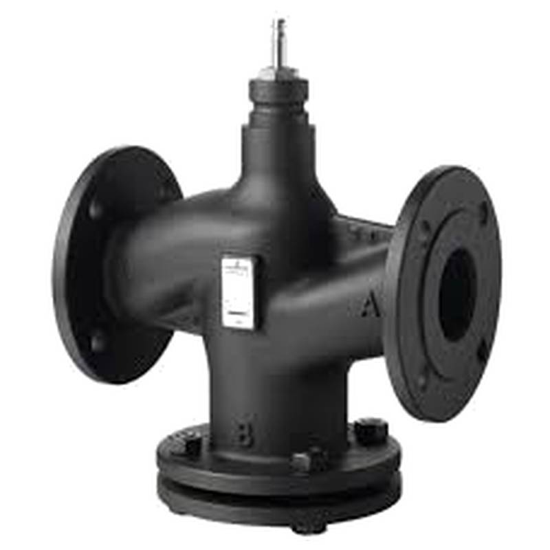
SIEMENS VVF47.125 Flanged Two-Way Valve DN125 High Flow


The SIEMENS VVF47.125 Flanged Two-Way Valve DN125 High Flow is a robust and precise control valve engineered for demanding industrial applications. This valve excels in providing accurate flow regulation, boasting superior sealing capabilities and exceptional durability. Its high flow capacity, coupled with a DN125 nominal diameter, makes it ideal for large-scale fluid control systems. Key technical parameters include a nominal pressure of PN16, a maximum differential pressure of 100 kPa (for water), and a temperature range of -10 to 150°C. The VVF47.125 features a DN125 flange connection, a Kvs value of 400 m³/h, and is designed for electronic or electro-hydraulic actuation.
Product Specifications
| Parameter | Value |
| :---------------------------- | :------------------------------------------ |
| Product Type | Flanged Two-Way Control Valve |
| Manufacturer | Siemens |
| Model Number | VVF47.125 |
| Nominal Diameter (DN) | 125 |
| Connection Type | Flanged |
| Nominal Pressure (PN) | PN16 |
| Maximum Differential Pressure | 100 kPa (for water) |
| Flow Coefficient (Kvs) | 400 m³/h |
| Temperature Range | -10 to 150°C |
| Actuation | Electronic or Electro-hydraulic |
| Sealing | Class A according to EN 60534-4 |
| Body Material | Cast Iron GG25 |
| Trim Material | Brass |
| Travel | 25 mm |
| Control Characteristic | Equal percentage |
| Connection Standard | EN 1092-1 |
Core Features & Market Positioning
The SIEMENS VVF47.125 distinguishes itself through its high-performance design, offering a superior Kvs value of 400 m³/h for its DN125 size, enabling substantial flow rates essential in many industrial processes. Its construction from GG25 cast iron provides excellent durability and resistance to corrosion in various environments, positioning it as a reliable choice for long-term, heavy-duty operations. The valve's equal percentage control characteristic ensures precise and stable flow regulation across its operating range, a critical differentiator for applications requiring fine-tuned adjustments. Furthermore, its Class A leakage rate, as per EN 60534-4, signifies minimal seat leakage, contributing to energy efficiency and preventing process upsets. This combination of high flow, precise control, and robust build quality establishes the VVF47.125 as a premium offering in the industrial valve market.
Key Application Scenarios
This high-capacity two-way control valve is extensively utilized in industrial heating, ventilation, and air conditioning (HVAC) systems, as well as in process control applications within the chemical and power generation industries. Its ability to handle high flow rates with precise modulation makes it exceptionally well-suited for controlling the flow of water, chilled water, and steam in large building complexes, industrial plants, and district heating networks. For instance, in power plants, it can be employed for controlling cooling water flow or steam regulation to turbines. In chemical processing, it is instrumental in managing feedstock or product flow where accurate volumetric control is paramount. The DN125 flange size is indicative of its application in larger piping systems requiring significant throughput.
Practical System Integration Guidance
Integrating the SIEMENS VVF47.125 into existing systems demands careful consideration of actuator selection and control signals. Siemens offers compatible actuators such as the SQX series for electro-hydraulic operation or the GLB series for electronic control, which must be correctly sized and configured to match the valve's travel and force requirements. Proper installation involves ensuring the valve is mounted in the correct flow direction, typically indicated by an arrow on the valve body, and that all flange connections are properly aligned and gasketed according to PN16 standards to prevent leaks. For electronic control, the input signal (e.g., 0-10 V or 4-20 mA) from a Building Management System (BMS) or Distributed Control System (DCS) needs to be configured to match the actuator's input, and the valve's travel range should be calibrated for accurate positioning.
Operation and Risk Mitigation
Safe and efficient operation of the SIEMENS VVF47.125 hinges on adherence to specified operating conditions and regular maintenance. It is crucial to operate the valve within its designated temperature range of -10 to 150°C and not exceed the PN16 pressure rating or the specified maximum differential pressure for the fluid medium. For water applications, the maximum differential pressure is 100 kPa. Risks such as cavitation can occur if the differential pressure across the valve is too high, potentially leading to damage. Regular visual inspections for leaks, proper actuator function checks, and periodic cleaning of strainers upstream of the valve can mitigate operational issues. While specific fault codes are actuator-dependent, any noticeable deviation in performance, such as incorrect positioning or unusual noise, should trigger an immediate investigation.
Scalability & Long-Term Value
The SIEMENS VVF47.125 offers significant long-term value through its robust construction and compatibility with Siemens' broader automation portfolio. Its standard flange connections (EN 1092-1) ensure broad compatibility with various piping systems, facilitating seamless integration or replacement. The valve's ability to work with advanced electronic actuators opens pathways for integration with modern Industrial Internet of Things (IIoT) platforms, enabling remote monitoring, diagnostics, and predictive maintenance. As industrial processes evolve, the valve's precise control characteristics and high flow capacity provide a scalable foundation for increased demands. Future upgrades might involve transitioning to more sophisticated digital control strategies or integrating with asset management systems that leverage the valve's operational data for optimization and efficiency improvements.
FAQs
What is the primary function of the SIEMENS VVF47.125 valve?
The SIEMENS VVF47.125 is a two-way control valve designed for precise regulation of fluid flow. Its primary function is to modulate the volume of liquid or gas passing through a pipeline system.
This valve is particularly suited for applications demanding accurate process control and a high flow rate. It ensures stable and repeatable system performance by maintaining desired flow conditions.
Its robust design and high Kvs value make it ideal for large-scale industrial and HVAC applications where precise flow management is critical for efficiency and safety.
What are the typical pressure and temperature limitations for the SIEMENS VVF47.125?
The valve has a nominal pressure rating of PN16, indicating it can withstand pressures up to 16 bar. For water applications, the maximum differential pressure is limited to 100 kPa.
Operating temperatures for the VVF47.125 range from -10°C to 150°C, making it suitable for both heating and cooling circuits. Adhering to these limits ensures valve longevity and operational safety.
Exceeding these specified pressure or temperature limits can lead to premature wear, leakage, or catastrophic failure of the valve and connected system components.
How does the Kvs value of 400 m³/h benefit system design?
A Kvs value of 400 m³/h signifies a substantial flow capacity for a DN125 valve. This allows for higher throughput in the system compared to valves with lower Kvs ratings.
This high flow coefficient means a larger volume of fluid can be controlled by a single valve, potentially reducing the number of control points needed in large systems. It also means the valve can handle significant system demands effectively.
Engineers can leverage this high Kvs to design more compact systems or to ensure sufficient flow is available for peak operational requirements without oversizing other components, contributing to system efficiency.
What type of actuation is compatible with the SIEMENS VVF47.125?
The SIEMENS VVF47.125 is designed for compatibility with both electronic and electro-hydraulic actuators. This offers flexibility in system design and implementation choices.
Siemens provides a range of compatible actuators, such as the SQX and GLB series, which can be selected based on specific application requirements for force, speed, and control signal.
Proper actuator selection and matching are crucial for achieving the desired control accuracy and ensuring the valve operates within its designed parameters for optimal performance.
What does "Equal Percentage" control characteristic mean for this valve?
An "Equal Percentage" control characteristic means that for equal increments of valve travel, the change in flow rate is proportional to the flow rate at the beginning of the increment. This results in a more linear relationship between valve position and flow at higher openings.
This characteristic is advantageous for maintaining stable control over a wide range of flow rates. It ensures that small adjustments at lower flows have a comparable impact to small adjustments at higher flows, preventing drastic changes.
This feature is vital in applications where precise flow modulation is required across varying demand levels, ensuring consistent process conditions and energy efficiency throughout the operational spectrum.
What are the implications of Class A sealing for the VVF47.125?
Class A sealing, as defined by EN 60534-4, indicates a very low level of leakage when the valve is in its closed position. This is often referred to as "bubble-tight" or near-zero leakage.
Such tight sealing is crucial for energy conservation, especially in heating and cooling systems, as it prevents unwanted heat transfer or flow when the system is not actively calling for it.
This specification minimizes process losses and ensures accurate flow control by preventing even minimal flow bypass when the valve is commanded to shut off, contributing to overall system efficiency and stability.
What materials are used in the construction of the SIEMENS VVF47.125?
The valve body is constructed from GG25 cast iron, which provides robust mechanical strength and good resistance to corrosion in many industrial environments. The trim components are made from brass.
These materials are chosen for their durability and suitability for handling a wide range of industrial fluids, including water and certain other compatible media.
The combination of cast iron and brass ensures a balance between structural integrity, cost-effectiveness, and performance in typical operating conditions encountered in industrial HVAC and process applications.
Can the SIEMENS VVF47.125 be used with steam?
Yes, the SIEMENS VVF47.125 can be used with steam within its specified operating temperature range of -10 to 150°C and pressure limitations. For steam service, it's critical to ensure the differential pressure does not exceed recommended limits for steam applications.
When used with steam, it's important to consider steam-specific factors like potential for water hammer and ensure proper installation with appropriate steam traps and condensate drainage to protect the valve and system.
Consulting the detailed product documentation or Siemens technical support for specific steam application guidelines is highly recommended to ensure optimal performance and longevity.
What is the flange connection standard for this valve?
The SIEMENS VVF47.125 utilizes a flanged connection according to the EN 1092-1 standard. This is a widely recognized European standard for flanges.
This standard ensures compatibility with other flanged components manufactured to the same specification, simplifying integration into existing piping infrastructure and facilitating system assembly.
When installing, ensure that the mating flange and gasket also conform to EN 1092-1 and the PN16 pressure rating to guarantee a secure and leak-free connection.
How can I ensure proper installation and prevent leaks with the VVF47.125?
Proper installation involves ensuring the valve is oriented correctly according to the flow direction arrow and that flange faces are clean and free of debris. Use the correct type and size of gasket specified for PN16 flanges and the fluid being handled.
Tighten flange bolts systematically and evenly in a star pattern to ensure uniform pressure distribution across the gasket. Avoid over-tightening, which can damage the flange or gasket, or under-tightening, which can lead to leaks.
Regularly inspect the flange connections for any signs of weeping or leakage after installation and during operation, especially after initial system startup or temperature changes.